Overview
Liquid cooling is emerging as a critical technology in data centers due to the increasing heat and power demands from advancements in CPU and GPU processing capacities. Traditional air-cooling methods are no longer sufficient to manage the thermal loads (Thermal Design Parameters TDP) generated by modern high-performance computing and AI workloads.
The liquid cooling market is projected to grow significantly, reaching $14 billion by 2031. Key liquid cooling technologies include Rear Door Heat Exchangers (RDHx), Direct to Chip (DTC) cooling, and Immersion Cooling, each offering distinct benefits in efficiency, density, operation and maintenance.
Advantages of liquid cooling include improved DC performance, enhanced energy efficiency, and better space utilization. Liquid cooling can significantly reduce the Power Usage Effectiveness (PUE) of data centers, reduce footprint, contribute to lower operational costs, and reduce environmental impact.
Implementing liquid cooling in existing data centers involves adopting hybrid approaches, combining both air and liquid cooling to handle varying workload densities. New data center designs must cater for high-performance computing (HPC)/high-density rack configurations and integrate liquid cooling infrastructure from the outset, ensuring scalability and futureproofing. Liquid cooling represents a pivotal shift towards more efficient and sustainable data center operations.
Introduction to the GPU era
The rapid evolution of artificial intelligence (AI), high-performance computing (HPC), and data analytics workloads have necessitated significant advancements in CPU and GPU technologies. While driving performance to new heights, these advancements have also led to substantial power consumption and heat generation increases.
In terms of power consumption, modern server CPUs can have a thermal design power (TDP) of up to 400 watts, while high-end GPUs used for AI and HPC can have TDPs of up to 700 watts, with future projections reaching up to 1 kW per GPU.
The system configuration of servers also affects the change, having servers come in various form factors (2U, 4U, 8U) and can house multiple CPUs and GPUs. For instance, a single system could contain 2 CPUs and 8 GPUs. Such a system might require between 7 kW to 10 kW of cooling capacity just for the CPUs and GPUs. A standard server rack can accommodate around 8 such high-performance systems, which translates to an estimated total thermal load of 56 kW to 80 kW per rack, potentially reaching up to 100 kW and more.
This significantly higher IT processing capabilities, also impose a serious challenge on data center operators, where equal capacity of heat shall be removed by the DC cooling system. Liquid cooling (LC) is a suitable cooling technology ready to be implemented for current short-term needs and future data center developments.
Boost sales and engage shoppers – Free Trial.
Transform product descriptions into stories that convert shoppers into buyers.
Market Status and Future Trends
The demand for increased cooling efficiency, energy savings, and higher performance primarily drives the data center liquid cooling market. Although systems scalability and sustainability are the main concerns for data center development, the current main purpose is the continuously increasing demand for highly dense workloads and extreme heat dissipation. Increased streaming, processing, and data storage have been followed by more powerful CPUs/GPUs and equally higher heat removal needs.
As traditional air-cooling systems have started reaching their limits in terms of temperature range and cooling density, liquid cooling appears as the appropriate technology to deal with new powerful IT systems with high TDPs. The data center liquid cooling market share is currently evaluated in the range of 2.5 to 4 billion USD (2023) and is expected to reach values equal to 7.5 billion USD in 2028 and up to 14 billion USD in 2031. This means a predicted mean compound annual growth rate (CAGR) of 24%.
Similarly, the data center cooling market, estimated in 2023 with a market share of 13 to 15.5 billion USD, is expected to reach a value equal to 29 billion USD by 2030, under a CAGR of 12%, just half of that for liquid cooling technologies.
These figures indicate a clear and dynamic move towards liquid cooling as the main or only cooling system solution for existing and new data centers. Combining these data with the expected CAGR for GPU global data centers market development with GPUs for cellphones, cars, and edge IoT applications drives the growth rates and the intensive adoption of LC in the data center industry. So, the first question is how many and what kind of LC technologies are market-ready and under what conditions are available for implementation.
Liquid Cooling Technology
Rear Door Heat Exchanger (RDHx)
Rear door heat exchanger system can form the foundation for a hybrid approach to existing or new data centers where liquid and air-cooled systems exist together with mixed rack densities. This system provides a viable solution for managing densities above 20 or 30 kW and up to 50-60kW per rack, where the air-based cooling systems lose their effectiveness.
The RDHx is directly mounted on the back side of the ITE rack and sucks air from the data hall, makes it cool and directly discharge it into the mounted servers providing high cooling performance. The RDHx or chilled door contains fans, heat exchanger, and a circulating coolant. The coolant circulates through the exchanger, absorbs the heat, providing cool air to the ITE and the hot liquid is returned through the facility chilled water network back to the chiller(s) to reject the transferred heat.
RDHx reduce the airflow required for a data center and is the least disruptive solution for existing facilities. It can be installed when high density racks need to be implemented as long as routing of main pipe runs can be provided either through the raised floor or trenches. If pipes have to run overhead care must be taken to ensure some kind of leak prevention system provided by the CDUs.

Fig.01 – Typical arrangement of RDHx, DTC rack installation and associated CDU, along with the primary facility water and secondary ITE coolant networks.
Direct to Chip (DTC) or (D2C)
Direct-to-chip (DTC) cooling technology has higher heat removal capacities than rear-door heat exchangers. This cooling method uses a thermal transfer material to conduct the heat from the top of the CPUs, GPUs, and memory modules to a cold plate via a liquid flowing through this plate. The cooler liquid picks up the heat from the chip and is carried away to be cooled and returned in a closed-loop system.
This system does not remove 100% of the ITE equipment heat. Only 70-75% is achieved as the cold plate is not applied to other server components such as power supplies and IC capacitors. In this case, airflow is still required to cool the remaining 30%. Accordingly, DTC Cold plate technology can be integrated with new RDHx or existing air-cooling systems inside the white space.
The main components of the DTC system arrangement are the cold plates and flexible hoses connecting the cold plate with the supply and return manifolds, with the latter also installed within the rack. Each rack supply and return manifold are connected through a main pipe run with the coolant distribution unit (CDU) having redundant pipes and concurrently maintainable hydroponics. The CDU acts as the heat exchanger between the DC primary chilled water network and the ITE secondary coolant network and is installed in the cooling corridors, along the row, and within the rack in some cases.
Immersion Cooling

Fig.02 – Typical arrangement of single-phase immersion cooling tank installation and associated CDU, along with the primary facility water and secondary ITE coolant networks.
Servers and other components in immersion cooling are submerged in a thermally conductive dielectric liquid. This method eliminates the need for air cooling, including the fans within servers, leading to significant improvement in data hall noise levels.
Immersion liquid cooling is divided into “single-phase” and “two-phase,” with the latter not further examined as the technology faces several health and environmental constraints that have discouraged vendors from further development. In single-phase immersion cooling, servers are installed vertically within a thermally conductive dielectric bath.
Heat is transferred to the coolant through direct contact with server components and removed by a heat exchanger inside a CDU. The CDU will typically be a separate component located in proximity to the immersion tank or at the perimeter of the white space. However, immersion tanks are also available with integrated CDUs, providing a complete, self-contained cooling solution for high-density edge applications or multi-tank arrangements for large IT capacities and high-density workloads such as crypto mining.
This approach maximizes the thermal transfer properties of liquid and is the most energy-efficient form of liquid cooling. Coolant control is relatively simple in single-phase liquid cooling, and coolant loss is low with good sealing, thereby eliminating the demand for frequent coolant replenishment.
Advantages of Liquid Cooling
One of the main topics within the daily agenda of operators’ discussions for existing data centers is the upcoming challenge of higher workload demands and the consequent impact on data halls’ cooling. New approaches are continuously investigated, and information on available liquid technologies has become complicated.
Exploring Hybrid Cooling Solutions
Main concern remains the fact that all existing DC facilities operate under large to hype-sized air-cooled data halls using cooling technologies arranged in the perimeter of IT load. As air-cooled IT equipment is expected to stay in the front field for several more years, the operators are called to investigate a “hybrid” approach. A hybrid DC shall try to combine air and liquid cooling technologies to serve low and high-density loads simultaneously.
The approach for such a hybrid solution shall start from the data hall(s) workload planning. Operators shall record existing air-cooled IT along with the overall footprint and identify options for re-arrangement and grouping. This exercise aims to identify data hall-free space where high-density racks can be installed.
Implementing Liquid Cooling Technologies
Liquid cooling technologies like rear door heat exchangers or direct-to-chip liquid cooling are currently considered more appropriate for hybrid DC developments. Existing facilities with raised floors provide easy and direct runs for chilled water piping, which can be easily secured and controlled within a confined space. Dedicated rows of high-density racks will allow moving the CDUs directly next to the line and minimize the pipe runs.
Planning for Future Capacity and Efficiency
The million-dollar question then becomes how much space, infrastructure, and power/LC capacity to provide for the near future. DC operators should never forget that their facilities are not new, and most have already been run for many years. Increased power demand, potential difficulties in facility capabilities, and public authority constraints can easily be managed with facility power demand evaluation and re-planning. Adaptation of liquid cooling has a significant impact on cooling performance and system efficiency. The power demand for mechanical loads is expected to drop between 30-40%, and obviously, this saving can be redistributed to the new racks’ power supply.

Fig.03 – Indicative comparison of power demand, system efficiency, and OPEX savings for standard IT capacity for typical liquid vs air-cooled solution.
Space Utilization
The density enabled by liquid cooling will allow for the maximization of the data hall space utilization. LC technologies obviously are driven by higher rack density rates but, on the other hand, bring the cooling system closer to the rack and eliminate large footprint equipment like CRAH/AHU/FAN WALL units standing at the room perimeter. Existing facilities will better use their space, will free up currently non-IT occupied zones, and, in general, will reduce the need for expansions or new construction.
Personnel Working Environment
Working conditions within the IT environment will significantly improve as increased room temperatures and lower noise levels are direct consequences of LC adoption. Since the cooling will be directly onto or around the chip, server air cooling will reduce to 60% or be eliminated, respectively. This will allow the raising of room temperatures, creating a more comfortable environment, and at the same time, the lower fan speeds or elimination will allow a more sustainable noise level.

Fig. 04 – Reductions due to adoption of liquid cooling solution.
Liquid Cooling Infrastructure
Whether rack-mounted equipment is cooled indirectly through rear-door heat exchangers or directly through conductive DTC or immersive technologies, dedicated infrastructure is required to create a continuous cooling fluid flow. Two liquid circuits are applicable to enable heat transfer between IT and the facility’s main heat rejection systems. A secondary circuit will circulate liquid to the IT cooling apparatus and, through a heat exchanger, will transfer the heat to the facility water network towards wet, dry or hybrid-type coolers, which will reject it to the external environment.
Properly configuring the cooling infrastructure is key to successfully transitioning to liquid cooling. When configuring a dedicated loop to support liquid cooling, consideration should be given to the ability of the infrastructure systems to ensure precise temperature control of the liquid being used for cooling, as well as the ability to respond to the sudden load, increases common in HPC environments. A dedicated liquid cooling infrastructure should also be designed to minimize fluid volume, reduce the consequences of leaks, and mitigate risks from pressure in the network. The main components of LC infrastructure depend on selected technology. In case of RDHx and DTC solutions, the coolant distribution units (CDUs) are the most essential part, while for immersion, the tank becomes the one and only component. The heat reduction plant is the last piece of equipment to complete the required infrastructure.
Coolant Distribution Unit (CDU)
Connection element between the rack distribution manifold and the primary facility water loop is the coolant distribution unit or CDU. CDUs are liquid-to-liquid heat exchangers that can be connected to the building’s chilled water system and allow heat rejection from IT to the external environment or district heating in cold countries for heat reuse.
Main purpose of the CDU is to keep the secondary IT liquid loop separated and isolated from the primary water network serving the whole facility and other critical areas. This way the CDU maintains temperature, flow and water quality across the IT network, achieving high system reliability and performance.
Typical cold plate passage of 0.1mm can easily get blocked and prevent chip cooling. This clarifies the importance of coolant filtering and overall quality control performed by the CDU. Also, precise coolant temperature control by the CDU provides regulated value above the room dew point and prevents condensation within the ITE. Coolant-controlled quality and chemistry prevent galvanic corrosion. In-row CDUs or rack mounted are available and considered a very effective and preferred solution.
For applications that do not have access to chilled water in the data center or prefer not to tap into the existing chilled water system, a modular indoor chiller provides efficient and reliable support for liquid cooling. Indoor chillers are stand-alone units designed to support liquid cooling and use the same footprint as perimeter cooling units to simplify retrofits and future-proof new data center designs. CDU built-in variable speed pumps allow the flow of refrigerant to adapt to changing loads and internal controls maintain the leaving water temperature by controlling the speed of the pump.

Fig.05 – Typical arrangement of main infrastructure components within a liquid cooling system, highlighting rack mounted and in row CDU, along with the primary facility water and secondary ITE coolant networks.
Coolant Distribution Manifold (CDM)
The CDMs are the distribution pipes that supply coolant to each server and collect the hotter coolant back to the CDU. Vertical manifolds are placed at the back of the rack and directly connected to the CDU through the IT coolant piping network. CDM is selected by the provided heat transfer capacity which shall be equal or more than the rack density. A normal manifold heat transfer is in the range of 100-200kW. Similarly, horizontal manifolds can be placed at the front of the rack in a 1U rack mount space. They connect the vertical manifolds at the rear of the rack to cold plates on systems with inlet and outlet hoses at the front of the rack.
Flexible hoses are used to supply and return the cold/hot liquid to the CPUs and GPUs from the manifolds. Couplings across the two ends shall be through high-performance Quick Disconnects (QD) each typically sized in the range of 4-6kW. Design of QDs is currently not controlled by any standard and the more connectors you have the higher the pressure drop. In contrast, special safety type design of QDs makes them more complicated and increases further the pressure drop. Selection of QDs and pipe sizing directly affect the system’s overall operation pressure and flow to/from the CDU.
Coolant inlet and outlet temperatures, along with total required flow rate and flow impedance, are design parameters that affect the sizing and arrangement of CDM and flexible hoses. Obviously, extremely high-pressure systems increase the risk of failure and leakage. Non-spill connectors are required with the system and liquid level sensor is recommended to be included.
Immersion Tank
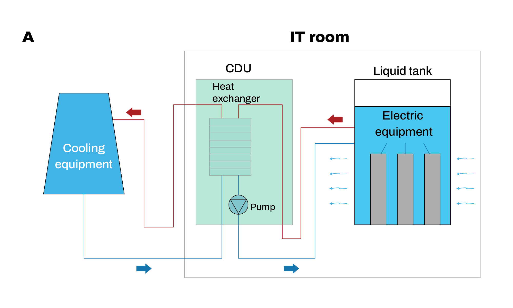
The immersion tank houses vertically mounted servers in a dielectric bath and circulates the dielectric fluid through a CDU to remove heat. Each tank is considered a module, and the size can vary from 60 to 300 kW. Part of the tank can also house single or redundant CDUs and dry zones around for direct access to the network and power (PDU) components. Arrangements of smaller size tanks can be stacked within properly designed rack units to allow smaller footprints like existing air-cooled racks. At the same time, these racks can serve as liquid containers during potential leakage.
As each tank is equipped with its own CDU, the modules can be directly connected to the facility water network through provided flow and return piping connections without any further intermediate unit. The liquid used for immersion cooling is non-conductive and non-corrosive, so it may be used with electronic components.
Each immersion cooling tank is standalone and compact, easy to deploy, especially for environments where the servers will be in a confined space without a data center infrastructure. However, traditional DC facilities can also fit within complex layouts and connect to a standard water loop. Immersion cooling tanks can provide AC or DC power supply (external rectifiers required), covering like this new market demand for DC-powered ITE.
Heat Rejection Unit
Heat rejection is through existing or new specific-sized dry coolers, air-cooled chillers, or hybrid coolers. The selection of the right type of heat rejection unit is based only on the external environment’s temperature range. Ambient temperatures of northern climates allow the use of conventional dry coolers, while for higher temperatures, hybrid solutions with water evaporation like cooling towers, is required. In areas where the ambient temperatures are very high and water is scarce, air-cooled refrigerant-based chillers operation is essential to support heat removal.
Using existing dry coolers or cooling towers for final heat rejection may be possible, but these systems often require modification to support liquid cooling. For example, depending on the location of the facility, the dry cooler may require an adiabatic assist to maintain the lower supply temperatures required for liquid cooling throughout the year.
Adoption of LC in Existing DC
One of the main topics on the daily agenda of operators’ discussions for existing data centers is the upcoming challenge of higher workload demands and consequent impact on data hall cooling. New approaches are continuously investigated, and information on available liquid technologies has become complicated.
The main concern remains that all existing DC facilities operate under large to hype-sized air-cooled data halls using cooling technologies arranged in the perimeter of the IT load. As air-cooled IT equipment is expected to stay in the front field for several years, the operators are called to investigate a “hybrid” approach. A hybrid DC shall try to combine air and liquid cooling technologies to simultaneously serve low and high-density loads.
The approach for such a hybrid solution shall start from the data hall(s) workload planning. Operators shall record existing air-cooled IT along with the overall footprint and identify options for re-arrangement and grouping. This exercise aims to identify data hall-free space where high-density racks can be installed. On the back of that, liquid cooling technologies like rear door heat exchangers or direct-to-chip liquid cooling are currently considered more appropriate for hybrid DC developments.
Existing facilities with raised floors provide easy and direct runs for chilled water piping, easily secured and controlled within confined spaces. Dedicated rows of high-density racks will allow the movement of the CDUs directly next to the line and minimize the pipe runs. The million-dollar question then becomes how much space, infrastructure, and power / LC capacity to provide for the near future. DC operators should never forget that their facilities are not new, and most of them have already been run for many years.
Increased power demand, potential difficulties in facility capabilities, and public authority constraints can easily be managed with facility power demand evaluation and re-planning. Adaptation of liquid cooling has a significant impact on cooling performance and system efficiency. The power demand for mechanical loads is expected to drop between 30% and 40%, and obviously, this saving can be re-distributed to the new rack’s power supply.
LC in new DC
Investment planning and buildup of a new data center are very complex projects, including simultaneously fulfilling several requirements and constraints. The factor that directly affects liquid cooling decisions is the design rack density. A straightforward but meaningful definition of density is how many chips we can fit into the same rack. A large number of powerful chips within new technology servers and onto multiple stacks create what we call high-density racks. Based on the services provided by the data center, different rack densities are expected, as shown in the table below.

The data market has also undergone changes, innovations, and high/low demand periods in the last two decades based on technology trends. In this case, using artificial intelligence (AI) and developing algorithms that can be trained on historical data center traffic loads is essential. Such models will easily predict expected trends since the model will be DC-specific and reflect local market trends, facility size evolution, and country social and financial conditions. The outcome obviously should not be used in absolute numbers but more as percentage trends. This will give the DC operators a reliable tool to predict the expected near and long-term needs of high-density and AI workloads.
Depending on how aggressive the selection of liquid cooling technology shall be will also affect the new DC design and development. The new DC design will have to provide chilled water piping to circulate water closer to the chip level, compared to the past, when water cooling infrastructure was at a distance and isolated.
Bringing the liquid coolant closer to the chip can increase the IT temperature and improve the DC efficiency. These new cooling technologies require different data hall arrangements and water system runs and affect operation. Creating a strong connection between the IT and the facility teams is a one-way road. Both have to work together within the same racks and have to coordinate their operation and maintenance activities in common. Furthermore, immersion cooling solutions also require a complete change of habits for the IT team as the servers are now immersed within the oily dielectric liquid. Any activity will follow different maintenance procedures than those used today with direct withdrawable dry servers.
Resolution of issues related to liquid leakage, CDU redundancy, pipe design pressure, and liquid quality to protect from cold plate blockages are essential technical issues under continuous investigation, and suppliers have offered several solutions already. Maybe the development of a new DC will also need to make some early decisions on the liquid cooling vendors and use their R&D details or request a design of a system customized for the specific layout and workload provision.
The quantification of redundancy and reliability of LC systems is of primary concern, as there are no currently certified solutions or widely accepted design standards. In this case, it becomes of high importance and market demand that respective development institutes and associations develop whitepapers or even more standards to describe acceptable topologies and architectures for certain tier levels of reliability.
Share this post
Theodosios Moumiadis
Principal Consultant
Theodosios is an MEP design engineer with over 20 years of experience. He provides consultancy in design, assessment, construction management, and supervision of Data Center site infrastructure, covering architectural/structural, electrical, mechanical, fire protection, security, and building management systems (BMS). He is responsible for the success of the Data Center Engineering operations across all undertaken projects and assignments.
Stay ahead
Is Your Data Center Site Truly Sustainable?
Sustainability isn’t just a buzzword; it’s about balancing environmental, social, and economic needs. At Edarat Group, we design smarter, greener data centers that harness solutions like rainwater harvesting to cut water waste and boost efficiency.


